Global Space Balloon Challenge
Background
The Global Space Balloon Challenge is one of the competitions Mizzou Space Program participates in. It is a projected associated with the national organization Students for the Exploration and Development of Space. This challenge tasks student teams with launching a high-altitude space balloon, with a choice of experiment and requirement of having a camera on board. I acted as project manager of this project for the 2020-2021 school year.
Development
An trait of higher altitudes is the lack of infrared light absorption due to the less-dense air. The experiment intended to take advantage of this by attempting to observe an astronomical body such as a planet or star. Unfortunately, the funding to purchase such a sensor was not attained. Instead, we focused on the other major component of the experiment: orientating a camera in an intended direction. The camera needed to sit on a platform that would stay level, and point in a specific compass direction. Platform stabilization was achieved by leveling it using low-temperature bearings (the expected temperature being as low as ~ -60 °C!). The gimbal used a servo motor controlled by a magnetometer, accelerometer, gyroscope sensor, and Arduino programing (thanks to David Huber for his great work with programing!)
Launch
The platform was wrapped in insulating material, and packed with hand warmers to keep temperatures at operating levels. We used an altimeter to record the maximum altitude and a GPS to track it's position. It started outside of Columbia, Missouri, and flew mostly east for 1 hour and 53 minutes, to land 98 miles away, a short way across the Mississippi river in Illinois.
The full video of the launch:
In one image below you can see the Mississippi River meeting the Missouri River where it runs past St. Louis.


Electronics Bay Sleds
BackgroundMizzou Space Program participates in a variety of projects, including the University Student Rocketry Challenge.
Competitors are tasked with achieving maximum altitude within a limited impulse. MSP's entry is a two-stage
rocket with an inner body diameter of approximately 1.15 inches. The sustainer stage coupler additionally acts as
an electronics bay, with an inner diameter of approximately 1.1 inches. In such a confined space, it is a challenge
to properly secure the electronics components. I developed a solution of designing and 3-D printing sleds for three
of the comments: the Apra altimeter, the Raven 4 flight computer, and the Raven 4 battery.
Development
Each component was designed in Solidworks. The Apra and Raven sleds are fairly similar. I measured their
dimensions, and the location of their securing screw holes. I transferred these measurements to a rectangular
platform in Solidworks. I then extend the length of the platform, to add circular loops on each end that fit the inner
diameter of the electronics bay. Triangular supports are also included to add rigidity. The ends of the model are
open to allow room for wiring.
Below are these two parts in Solidworks.


For the Raven 4 battery holder, I made a cylinder with the diameter that fits the electronics bay. I cut the
dimensions of the battery into the cylinder, with additional room for any expansion of the battery due to use.
Additional cuts are made into the model to to reduce material weight and allow for cooling. The image of this
component in Solidworks is not currently available.
I created a few iterations of each component, to achieve the best part quality, and to adjust the fit of the components outer diameter. The picture below show these iterations, with the first at the top, and
the final component, with its electronic component, at the bottom.

The image below shows the components next the coupler / electronics bay in which they fit, with the addition of a spacer that holds the magnetic switch.

The USRC rocket successfully launched and recovered.
Level Two Tripoli Certification
Background / motivation
The natural progression past level one in any challenge is level two. Given the access to Mizzou Space
Program’s materials and tools, I was given the opportunity to pursue this towards my Tripoli Rocketry
Association (TRA) membership. A level two certification allows a member to purchase high powered rocket
motors in the J to L range: or rockets with a total impulse between 640 to 5120 N⋅s . A member must pass a
multiple choice test, containing equal parts safety and technical questions. A rocket with a motor within the
range must launch and land in a condition fit for reuse.
Plan and Limitations
There were certain criteria specific to my certification. Firstly, I was given access to an Aerotech J425 redline,
with an impulse of 676 N⋅s and a burn time of 1.6 seconds. Since one wants a minimum speed off of the launch
rod (so that the fins can effectively provide stability), weight would be restricted to allow enough acceleration
to achieve this. I was most familiar to a duel deployment, center-separating configuration from previous
experience. Therefore I used this configuration for my rocket. I also made a rule for myself: no 3-D printed
parts. I did this to become more familiar with the classic manufacturing techniques, and to procure experience
for the club.
parts. I did this to become more familiar with the classic manufacturing techniques, and to procure experience
for the club.
Step by step construction
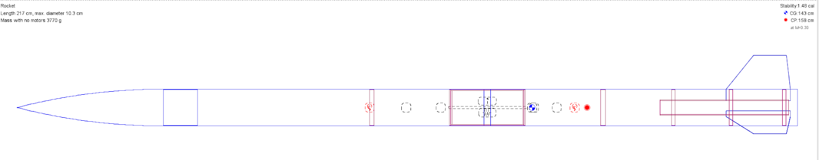
Before beginning actual construction, I wanted a sufficiently detailed design beforehand. I created an initial
mock up in Open Rocket, using the dimensions of real parts found online, from which I made a parts list.
mock up in Open Rocket, using the dimensions of real parts found online, from which I made a parts list.

I decided to hold off on finalizing any extra nose cone weight, which could be adjusted based on the real weight and center of mass of a near-complete assembly. Once the parts arrived, the construction process began.
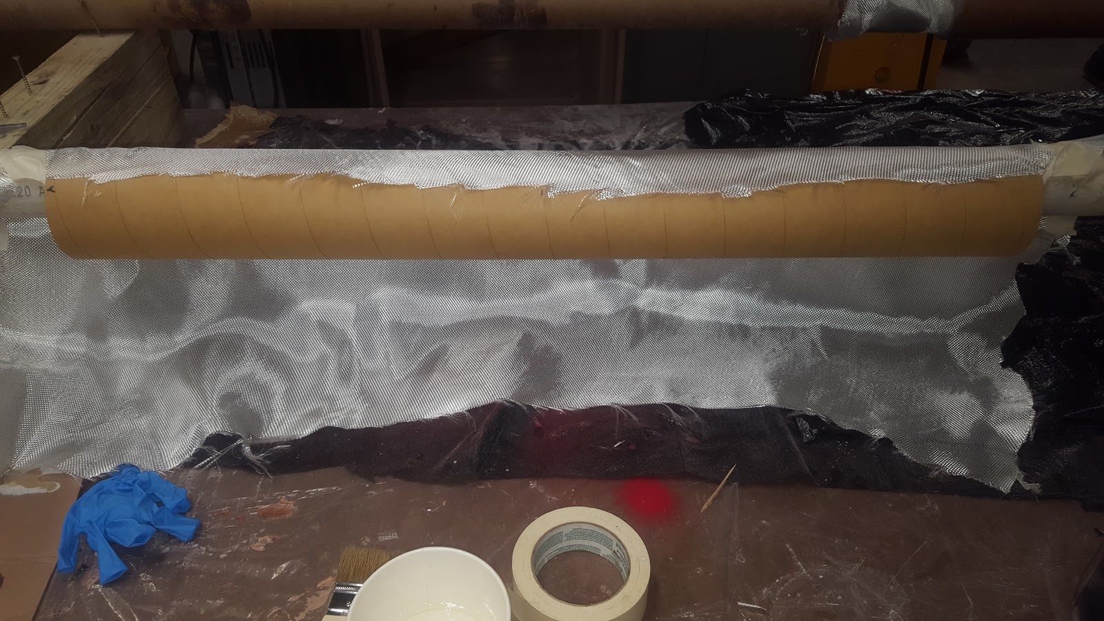
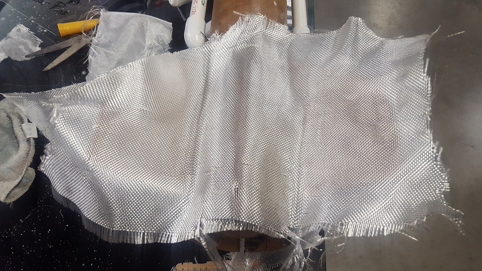
I wrapped the body tubes with a single layer of fiberglass, and coated them with two part epoxy.
If I were to make this again, I would rather use two layers of fiberglass.
If I were to make this again, I would rather use two layers of fiberglass.

Sanding is a long process, but must be done to remove imperfections in the fiberglass surface, and to provide
less drag.
less drag.

I attached centering rings to an inner tube. The inner tube would fit into the body tube. The motor would fit into
the inner tube.
the inner tube.

I cut three fins from plywood. Their shape was determined using open rocket, which could determine a center
of pressure. Using the estimated weight of parts, the program also provided a preliminary stability.
of pressure. Using the estimated weight of parts, the program also provided a preliminary stability.

The fins are tabbed to attach to the inner tube. This assembly is pushed into the aft body tube, with the finds
protruding through cut slots.
protruding through cut slots.


I then wrapped the fins with fiberglass.. This attaches the fins to the outer surface of the airframe, and provides
extra strength in flight.
extra strength in flight.
This shows the seam of the fiberglass wrap, and the filleted interface of the fins and airframe.

The coupler holds together the halves of the airframe using shear pins. Inside of it is the altimeter and battery.
The altimeter is programed to fire an ejection charge at the rocket’s peak altitude, to release the drogue
parachute, and then a second ejection charge a few hundred feet above ground, to release the main parachute.
The parachutes are attached by shock cord to either end of the coupler, and to their respective halves of the
airframe.
One end of the coupler is fixed with fiberglass, while the other is secured using two threaded rods.
These threaded rods provide necessary tensile strength for the force of parachute deployment, while also
holding the coupler together. The shock cords are attached to eye bolts, which are secured by a wooden bracket
to the threaded rods.
These threaded rods provide necessary tensile strength for the force of parachute deployment, while also
holding the coupler together. The shock cords are attached to eye bolts, which are secured by a wooden bracket
to the threaded rods.


Wooden bulkheads attached to the inside of each body tube using epoxy and fiberglass. Eyebolts were screwed
into each bulkhead to secure an end of a shock cord.
into each bulkhead to secure an end of a shock cord.

The altimeter and battery are secured to a wooden tray, and the tray is attached to both threaded rods.


The threaded rods tight on both ends of the coupler.
I attached wires from the altimeter attached to terminal blocks. These terminal blocks are then used to
complete a circuit with electronic matches. The wire’s holes are later taped up to isolate the inside of the coupler.
complete a circuit with electronic matches. The wire’s holes are later taped up to isolate the inside of the coupler.

I wired a rotating switch to the altimeter, and which protrudes through the coupler switchband. I would rather
not use this type of switch in the future, as it provided no physical indication as to whether it was in an on or off
position.
not use this type of switch in the future, as it provided no physical indication as to whether it was in an on or off
position.

The altimeter functions by sampling air pressure, and thus determining altitude. The coupler, functioning as the
electronics bay, uses a sampling hole dependent on the ebay dimensions. One can test the function of the
altimeter by attaching a vacuum to this sample hole. The altimeter detects a drop in air pressure when the
vacuum is turned on, which it interprets as take off. When the vacuum is turned off, it reads that air pressure is
no longer increasing, and that it has therefore reached apogee. I caried out this test twice to show that both
parachutes would be able to deploy.
I bent a metal bracket into a Z shape, which is screwed into the aft centering ring of the motor tube.
When the motor is inserted, it is prevented from falling aftward by this motor clip. The motor is prevented from
moving forward by its own lip. The force of takeoff is distributed through the center tube, to the centering rings
and airframe.
When the motor is inserted, it is prevented from falling aftward by this motor clip. The motor is prevented from
moving forward by its own lip. The force of takeoff is distributed through the center tube, to the centering rings
and airframe.

Two rollers are screwed into the body tube, which guides the rocket off the rail. A small hole is drilled between
the front bulkhead and nose cone, so that pressure within the body tube is equalized as the rocket climbs to a
higher atmosphere. This prevents the nose cone from being pushed out.
I then weighed the whole rocket, and found the center of mass at the edge of a table. I could then use this
weight and location to model the center of gravity in open rocket. The program uses the fin dimensions to
know the center of pressure. These two measurements determine the stability number. I determined that I
would need to add extra weight to the nose cone to increase stability. I did this by epoxying metal nuts
(an expensive option, but effective) into the nose cone. This weight moved the center of gravity forward.
With this, the construction of the rocket was complete. At the time, the movie Avengers: Endgame had just
been released, and in it, Iron Man plays an important role. I chose the color scheme to reflect his classic colors.
been released, and in it, Iron Man plays an important role. I chose the color scheme to reflect his classic colors.
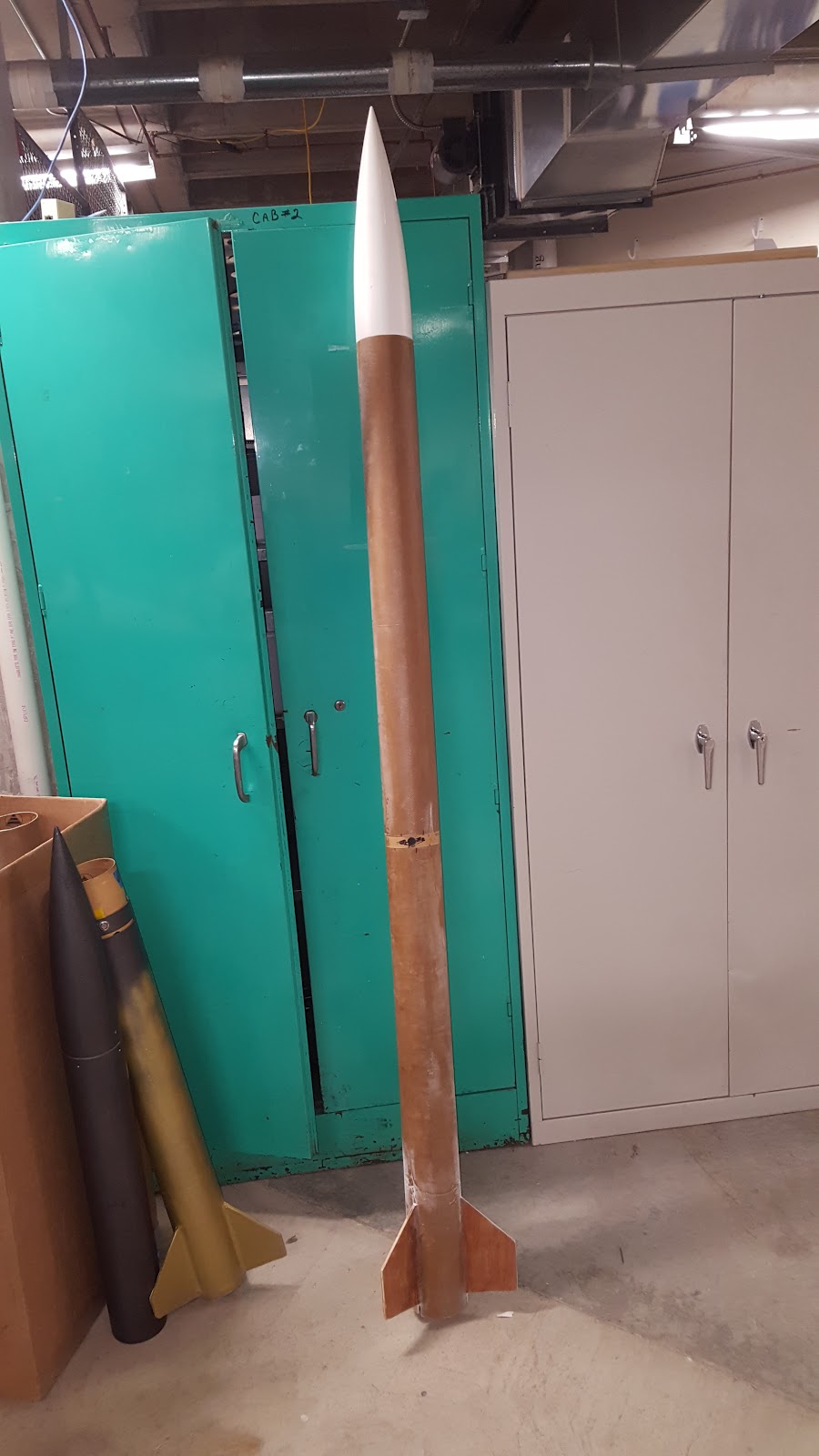

In an open rocket simulation, the software guessed the apogee would be at 2429 feet.

Launch day / results
On May 11th, 2019, Mizzou Space Program held their launch day at the MU Research Dairy Farm.
Preparations were made early in the morning, we travelled to the launch site, and commenced launching.
Under the supervision of Tripoli prefect Mark Grant whom we owe many thanks, club members certified
21 level one rockets. We then moved on to certifying 5 level two rockets, of which I was the last.
Initially, when the altimeter was turned on, the number of beeps it made (two) indicated that there was a
lack of continuity to one of the ejection charges. This required me to disassemble the rocket to examine the
electronics bay. I found that an electronic match had become detached from it terminal block. Back on the rail,
we counted down to launch . . . and nothing happened. After a safe pause, myself we replaced the ignitor with
a more reliable one. Another count down, and lift off!
The rocket shot towards the north east, into the wind. The ejection charge deployed at apogee, releasing the
drogue shoot. As it fell, the wind caused it to drift it back towards the launch site. The second ejection charge
also deployed, but no chute. It landed just 40 feet from where we were observing, with the nose cone stuck
vertically in the mud.
drogue shoot. As it fell, the wind caused it to drift it back towards the launch site. The second ejection charge
also deployed, but no chute. It landed just 40 feet from where we were observing, with the nose cone stuck
vertically in the mud.
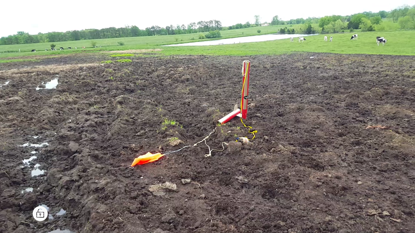
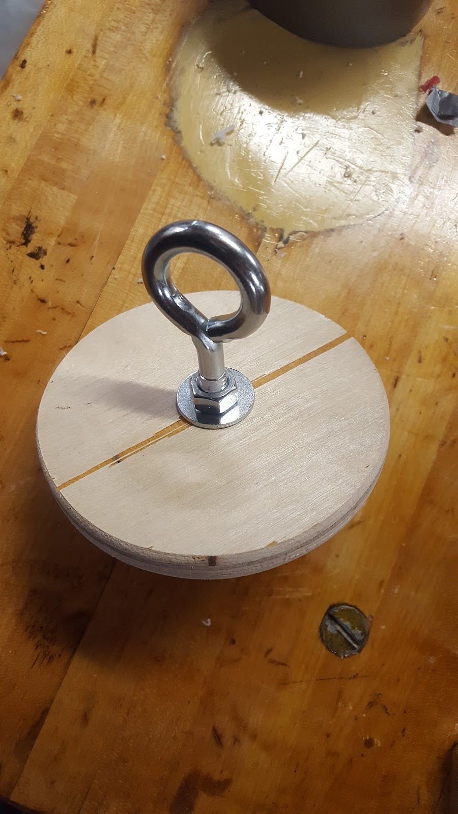
I discovered why the main parachute did not deploy. The eyebolt attaching the shock cord was not a solid piece.
Rather, the end of the ‘loop’ had a small space between it and the base. The parachute snaged onto it as if it
were a hook. It may be a small detail, but changed a large part of the intended flight.
Rather, the end of the ‘loop’ had a small space between it and the base. The parachute snaged onto it as if it
were a hook. It may be a small detail, but changed a large part of the intended flight.

However, the guidelines for a certifying flight do not require the deployment of two chutes. Rather, it must
land in condition to “fly again”. The prefect inspected the rocket, and gave the level 2 certification.
land in condition to “fly again”. The prefect inspected the rocket, and gave the level 2 certification.
Post flight, the altimeter uses beeps to communicate the maximum altitude of the rocket. In my case: 2,397 feet!

A club member edited together an amazing compilation of the launch day. It's too good to not share here:
Sources
My own photographs, and video taken by club members.
Level One Certification Rocket
In the fall of 2017, I joined the University of Missouri's "Rocket Club". As an introduction to the basics of rocketry, we certify through Tripoli. This organisation allows rocketry hobbyists to purchase increasingly powerful grades of commercial solid fuel motors, through a certification process. The first level requires the hobbyist to build a rocket that
- Uses a single H or I motor.
- Deploys at least single parachute
- Lands successfully with minimal damage.
In addition, A certifying authority must be present to " . . . witness the rocket ascend in a stable manner and descend in stabilized manner controlled by the recovery system." (tripoli.org) and confirm no excessive damage is sustained.
The design for this rocket was completed in a program called Open Rocket, which was the master thesis of a Finnish student named Sampo Niskanen in 2009. this is a wonderful program that allows hobbyists to simulate the flight of their design to know their expected apogee, top speed, and general success. Below is the design I eventually settled on. (updated picture needed)

The motor used for an Aerotech H115. It has a 1.5 second burn time, a total impulse of 172 newton seconds, and a mass of 205 grams (apogeerockets.com). A 30" cardboard body tube with a diameter of 2.56" is used. The motor is 29mm in diameter, and fits into the body tube using an inner tube. Two plywood washers are attached to either in of the inner tube, and glued to the walls of the body tube. this centers and holds the motor. The motor's nozzle is shaped to prevent the motor from sliding forward, and a plastic cap is and threading are attached to prevent the motor from falling out backwards

I used four wooden, trapezoidal fins. Open rocket has the capability of determining the position of the center of pressure of the rocket using the total surface area and shape of the fins, and quite likely other factors I don quiet yet understand. the location of the center of pressure and center of gravity are used to calculate the stability, witch is a simple ratio of the distance between them over the total length. the golden rule of rocket flight is to have the center of pressure further to the aft of the rocket then the center of gravity, and that the stability is an appropriate value for what you are doing. the stability of this rocket came out to be 1.4. Having a rocket with to high stability ratio (over-stable), means it has the potential to be to easily moved off it's flight path by a gust a wind. to low stability (under-stable) takes away the rocket's ability to correct itself.

Rail buttons are attached to the body tube, as well as a parachute anchor. One 10" square piece of canvas is attached using a nylon shock cord to the inside of the body tube, to act as the parachute.
Weight was added to the nosecone, to move the center of weight forward to reach the target stability.

Launch Day
Mizzou Space Program met at the MU Research Dairy farm to launch their space vision competition rocket and various certification rockets on Saturday, October 13th.
After many exciting and successful flights from the team, I was up next. With gracious guidance from the local Tripoli prefect Dr. Grant, we loaded the rocket onto the rail, and secured the igniter into the motor.
After many exciting and successful flights from the team, I was up next. With gracious guidance from the local Tripoli prefect Dr. Grant, we loaded the rocket onto the rail, and secured the igniter into the motor.

We moved back to the launch control station.

With a countdown, launch!
I started the video a moment to late, but I beautiful picture can be taken from it:

The motor burned out, and the aircraft coasted to it apogee. The motor, which had been previously been adjusted to delay a couple of seconds before firing, then ignited a charge that separated the nosecone, and released the parachute.
A picture was taken where it landed. It's typical practice to treat the landing site as a crime scene, and decipher what may have happen during flight. Here we can see the parachute looks almost completely twisted up. This is largely unavoidable without swivels, which are saved for larger projects.
A picture was taken where it landed. It's typical practice to treat the landing site as a crime scene, and decipher what may have happen during flight. Here we can see the parachute looks almost completely twisted up. This is largely unavoidable without swivels, which are saved for larger projects.

I was initially worried that a find or might break off during landing, which could have rendered the certification as a failure. Luckily, the ground was soft after rain, and the fins were only muddy.

I estimate the distance to the launch site to have been 200 - 250 feet.

In Conclusion
I am very happy with the results of this project. It is the first rocket built on my own, and I am grateful to have learned so much from the team members of Mizzou Space Program. I was happy to receive my level one certification card in the mail, soon after!